









Description
WWII Minneapolis-Honeywell C-1 Autopilot Directional Panel
Item Overview
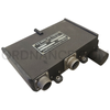
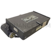
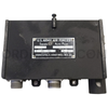
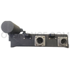
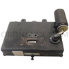
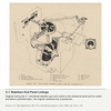
This U.S. Army Air Forces directional panel was part of the Minneapolis-Honeywell C-1 autopilot system used with the Norden bombsight. It translated mechanical heading movements into electrical steering commands. Its labeled cover, side plate, exposed mechanism, and projecting dashpot make it a detailed example of World War II aircraft flight-control equipment.
Identification and Features
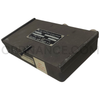
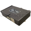
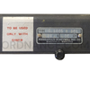
The cover and side plate carry separate identifying markings. These preserve the manufacturer, Army procurement information, electrical rating, and a specific equipment compatibility restriction.
- Manufacturer: Minneapolis-Honeywell Regulator Co.
- System marking: U.S. Army Air Forces, Series C1 Auto Pilot
- Cover plate type: G-1004-A
- Side plate type marking: G1005 B301
- Serial number on cover: AF45-H9788
- Order number: W33-038AC-6609
- Specification: C-24825
- Side plate electrical rating: 26 V DC
- Compatibility label: “TO BE USED ONLY WITH G1021B”
- Mechanism includes electrical wipers, sliding linkage, an adjustable dashpot, and two electrical connectors
Function
The panel received movement from the directional stabilizer's autopilot clutch arm through a sliding linkage. One rudder potentiometer produced rudder-correction signals, while two aileron potentiometers produced banking signals. A potentiometer is a variable resistor with a moving electrical contact, called a wiper. Movement of these contacts created the signals needed for coordinated rudder and aileron corrections, helping the aircraft return to its assigned heading.
Dashpot and Heading Stability
The projecting cylindrical assembly is an adjustable, liquid-filled dashpot linked to the rudder pickup. It changed the rudder response during sudden heading changes. Matching this response to the aircraft helped prevent repeated overshooting, known as oscillation or “hunting.” This small assembly addressed an important challenge in early autopilots: correcting a disturbance without creating an unstable series of corrections.
Documented End-Item Application
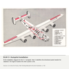
Army manual TM 1-413, Aircraft Instruments, dated June 1, 1946, documents this component as the directional panel. Figure 195, Interior of directional panel, appears on page 150. The manual places the unit on the left side of the bombsight's directional stabilizer. At the parent-system level, documented C-1 applications include the B-17 Flying Fortress, B-24 Liberator, and B-29 Superfortress.
Product History
Honeywell's surviving engineering records include a 1944 report titled Directional panel general performance, cataloged as C1-148. This places the component within the company's wartime development and testing work. Its detailed treatment in the June 1946 Army manual also shows its place in technical instruction immediately after World War II. The markings on this example preserve useful identifiers for comparison with those period records.
Parent-Equipment History
The Army sought closer electrical integration between the Norden bombsight and automatic flight controls as its bomber program expanded. Minneapolis-Honeywell developed the C-1 for that purpose. U.S. Navy historical records date its production order to October 1941 and describe it as standard equipment for the rest of the war. The complete system combined gyroscopic sensing, electrical signal processing, and powered servos connected to the aircraft's flight controls.
Weapon-System Background
The Norden bombsight helped bombardiers calculate when to release their bombs. Accurate aiming depended on a steady aircraft and close control of its course. Linking the bombsight with the C-1 allowed the aircraft to follow the bombardier's steering corrections during the bombing run. This connection became an important part of the Army Air Forces' high-altitude bombing system. Weather, turbulence, and sudden movement under combat conditions could still affect the results.
History of Use
The C-1 helped reduce pilot fatigue during long flights and steadied the aircraft for bombing. Either the pilot or bombardier could direct the system as needed. Its service extended across major Army Air Forces bomber types. C-1-equipped B-29s included Enola Gay and Bockscar, the aircraft used in the atomic-bomb missions of August 1945.
Condition
The item includes the marked panel and cover described above. The identification plates and mechanical features are useful details for study and display. Please check the pictures for the general condition of the item.
Ideal For
The panel's electromechanical design suits exhibits explaining how early autopilots linked mechanical sensing with electrical control. Its data plates also support research into wartime Honeywell equipment and Army Air Forces procurement.
- Norden bombsight and directional-stabilizer displays
- Minneapolis-Honeywell C-1 autopilot collections
- B-17, B-24, and B-29 equipment exhibits
- World War II avionics and automatic-control history
- Military museums and technical reference collections
Approx length 8", Approx width 6", Approx height 3", Approx weight 2.7lbs.
Please visit our page about order lead times here: Order Lead Times.